I think they are only needed on the ignition channels. Inputs should be fine, IMO.
As far as inverting the RPM input, I would suggest that the default install is inverted for the hall sensor. Since they are pulled up to 5V and ground when there is a window or tooth (depending on type), I think the input should be inverted. meaning that a +5V would mean a tooth and not lack of a tooth on the input pin of the uP. (for a windowed disc/wheel, it is the windows that are the point as well and not the disc material that masks the magnet). For a Hall, I cannot conceive of one that is better non-inverted. Also, I think we are all talking about optos for hall? Is that right? Is it really necessary? A BJT 2n3904 would work just as well and still keep the pin protected? I am fine with either, just bringing it up.
I think the L1815 is already +5V when there is a tooth, so it would be fine as is without inverting.
another option would be to have an opto for halls and add the components for the VR if required. In this install, you would have to have an opto that was configurable as inverting or non. If the pin uses an NPN, we could have the base with a configurable jumper to be pull up or pull down as our inversion detail?
Gearhead
Configurable polarity of I/O

Re: Configurable polarity of I/O
Upon reflection of what you have said, you are dead right. The software can be fixed and the hardware can be more or less fixed and we are good to go :-)
Here is what I have :
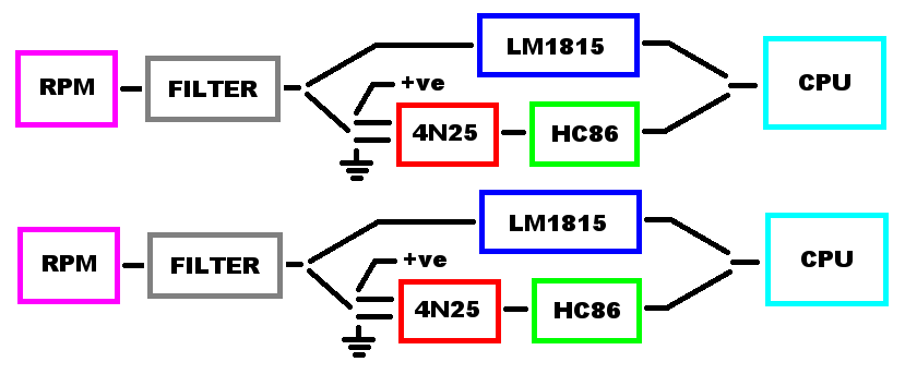
Note, the LM1815 is capable of handling a digital signal, the output of the hc86 *could* enter that if it is more convenient to route. If that is done and the user doesn't want to install the lm1815s for cost reasons, it can be jumpered across easily. Pin 11 configures whether to accept VR or digital input. Pin 9 is the digital input.
Opto couplers go low when a signal is applied, so we need to invert that. If we set it up as in the diagram then the opto provides some noise isolation, and the 86 inverts (or not) its output from go low to go high. If the opto is left with each pin configurable to ground/IN and IN/power then we can handle any digital signal thrown at us.
I think you are right in that the lm1815 shouldn't get an option to invert as it is always correct by default. Putting the option there will cause someone to use it when they shouldn't be :-)
Fred.
Here is what I have :
Note, the LM1815 is capable of handling a digital signal, the output of the hc86 *could* enter that if it is more convenient to route. If that is done and the user doesn't want to install the lm1815s for cost reasons, it can be jumpered across easily. Pin 11 configures whether to accept VR or digital input. Pin 9 is the digital input.
Opto couplers go low when a signal is applied, so we need to invert that. If we set it up as in the diagram then the opto provides some noise isolation, and the 86 inverts (or not) its output from go low to go high. If the opto is left with each pin configurable to ground/IN and IN/power then we can handle any digital signal thrown at us.
I think you are right in that the lm1815 shouldn't get an option to invert as it is always correct by default. Putting the option there will cause someone to use it when they shouldn't be :-)
Fred.
DIYEFI.org - where Open Source means Open Source, and Free means Freedom
FreeEMS.org - the open source engine management system
FreeEMS dev diary and its comments thread and my turbo truck!
n00bs, do NOT PM or email tech questions! Use the forum!
The ever growing list of FreeEMS success stories!
FreeEMS.org - the open source engine management system
FreeEMS dev diary and its comments thread and my turbo truck!
n00bs, do NOT PM or email tech questions! Use the forum!
The ever growing list of FreeEMS success stories!

Re: Configurable polarity of I/O
How about just using a tri-state buffer since we need a buffer anyway, to take care of undesirable/indeterminate bootloader/reset state potentials.
Hold outputs in the 3rd-state (puts all outputs in high-imp) by pulling the appropriate buffer pin, until the MCU is out of bootloader , then overwrite this pin with firmware.
Some of these IC buffers also come with inversion pin (i.e potential on that pin controls whether all buffered outputs are inverted or not) and 'jumper' this pin if desired to hardcode the inversion in hardware
Alex
Legal disclaimer for all my posts: I'm not responsible for anything, you are responsible for everything. This is an open and free world with no strings attached.
Re: Configurable polarity of I/O
Question. Why do we need the Opto? My understanding is it was used as protection in the MS because fuel only users could trigger from the coil.Fred wrote:Here is what I have :
previously: ca7
Re: Configurable polarity of I/O
No particularly good reasons I suppose, and possibly some invalid ones. I was throwing it up to be attacked :-)ca7 wrote:Why do we need the Opto?
Isolation of ground
Less susceptible to noise on the input (is this valid?)
Isolation of input polarity from output polarity - current flowing through the input always produces a low output, thus you can set up the polarity of a "signal" independent of what form that signal is in and handle the two forms of inputs independently of what the output is.
Do any of these three make sense at all?
That is correct for them, yes.My understanding is it was used as protection in the MS because fuel only users could trigger from the coil.
I guess provided it goes through the XOR then the CPU is isolated enough. Another advantage of the opto is that you can throw 15v or 5v into it and still get the same signal out. If you have just a logic gate you need to protect it and condition the input to some extent. The LM1815 handles raw inputs pretty well without much conditioning so my thoughts were that it would be nice to have the same ruggedness on the binary input.
Please shoot holes through everything I said as I'm pretty tired.
On another note. I was just experimenting with the board and port A goes high momentarily out of reset. This is one of the ignition channels and I had earmarked it for the fuel pump relay control as well. I'll need to reassign the pins around a bit and post up about it.
I'll do some more checking and add some columns to the pin out document that describe the reset and bootload behaviour of all pins so we can make some intelligent choices about what does what.
Ironically port B doesn't do that during reset. Perhaps the simplest thing to do is just reverse the pin to cylinder scheme again so some port B pins are free for relay duty etc.
We will need to do as suggested by you, ca7, and use the disable pins on the tri state buffers to remove power from the ignition pins such that they can't spark during reset.
Fred.
DIYEFI.org - where Open Source means Open Source, and Free means Freedom
FreeEMS.org - the open source engine management system
FreeEMS dev diary and its comments thread and my turbo truck!
n00bs, do NOT PM or email tech questions! Use the forum!
The ever growing list of FreeEMS success stories!
FreeEMS.org - the open source engine management system
FreeEMS dev diary and its comments thread and my turbo truck!
n00bs, do NOT PM or email tech questions! Use the forum!
The ever growing list of FreeEMS success stories!

Re: Configurable polarity of I/O
I've been trying to follow the threads, but lately I'm in a time crunch, so I've had to skim a fair bit of it. What is the outcome of the above? It appears it has settled down for now.
Is the big change to add an HC86 for signal inversion on the hall input?
I see the filter, what is it?
Is the ve+ where the hall would go?
Damn gotta go to work.
Is the big change to add an HC86 for signal inversion on the hall input?
I see the filter, what is it?
Is the ve+ where the hall would go?
Damn gotta go to work.
Re: Configurable polarity of I/O
I'm planning on the 74HC367 Newark 08F6507 for the ignition drivers, and the 74HC08 Newark 45J1285 (SMD) and Newark 18C7592 (thru hole) for the RPM inversion.
To recap, the above mentioned chips include 74HC01 (NAND), 74HC08 (AND), 74HC367 (NAND), 74HC125 (bus buffer), 2n3904 (drive transistor).
Hmmm, perhaps a quad chip for 2 RPM signals is a bit unnecessary... If we need it I don't mind tossing it in. I'm sure it can find uses.
Am I correct that the above conclusion was for ignition buffers, and RPM inversion? Or did I miss something up there?
I'm also planning on hardwiring all of these one way, but leaving it easy to break a trace and make a small jumper. What way should I default to?
Perhaps we should move this thread into the hardware forum. I had a heck of time finding this again. Kept looking in the wrong place(s).
Re: Configurable polarity of I/O
ok, the and and nand gates are useless for us. the 367 is a tri state, not a nand, and you forgot the 74hc86 XOR which IS useful for us :-)
The XOR chips will buffer AND invert, so if we need inversion, they are enough. If they can be had in an 8 pin part for input, sweet, if not, not a big deal either. the extra pins should have solderable points for jumper use though, waste not want not etc.
hardwired is fine for ign and injection controls and the fuel pump relay drive
the injector and fuel pump relay drive should all ground with the CPU pin high. Are we using Delta's injector driver scheme or going for high Z only as most of seem to think is "OK"? certainly with 400 parts already on board it might be a good idea to KISS this time round, thoughts?
The igbts should also ground by default with the cpu pin high. This is through the XOR chip and/or buffer though, so the default instructions for those should be to set them up for that mode and the layout making it easy without making the opposite hard. three closely placed pads with square edges as Jean suggested would make bridging the extra XOR input pins to ground or 5v pretty easy without anything except solder.
The XOR part numbers are all based around 74xx86, the ones easy to get for me are :
MM74HC86N = 74hc86
SN74ACT86N = 74act86 (more modern, but much the same?)
http://nz.farnell.com/jsp/search/browse ... stid=62287
If XOR isn't used for the buffer on the ign channels, the buffer chosen needs to have a drop in inverted replacement.
Given that the injector and fuel pump channel (which I still have to find a new pin for) will be low at all times unless commanded on I don't think we need the tri state setup to disable them so they can be driven directly with a 1k resistor and 100k to ground resistor. Because the ignition pins will be relying on a particular state being asserted I think using a tristate to "disable" them is a bad idea.
Fred.
DIYEFI.org - where Open Source means Open Source, and Free means Freedom
FreeEMS.org - the open source engine management system
FreeEMS dev diary and its comments thread and my turbo truck!
n00bs, do NOT PM or email tech questions! Use the forum!
The ever growing list of FreeEMS success stories!
FreeEMS.org - the open source engine management system
FreeEMS dev diary and its comments thread and my turbo truck!
n00bs, do NOT PM or email tech questions! Use the forum!
The ever growing list of FreeEMS success stories!
-
davebmw
- LQFP144 - On Top Of The Game
- Posts: 331
- Joined: Sun Jul 13, 2008 2:58 pm
- Location: South Wales, UK
Re: Configurable polarity of I/O
I would like to see the opto coupler after the LM 1814 and just before the port on the MCU.
Reason being if you are using the VR sensor and the LM1814 dies and shorts the 100V pulses directly toward the MCU i would rather it blow up the cheap and readily available opto coupler and not the lovely MCU.
Kill 2 birds with one stone use an opto schmitt coupler like HCPL7611 and jumper in the LM1814 for VR or bypass for hall sensor input. that would afford VR/Hall functionality with protection with reduced component count.
93'BMW 325is M50B25TU, Rebuilt 06/06, JE10.5:1, polish&port. Scorpion BB, K&N CAI, TEJ21 WBO2, '07 M3 Evo 18" 225F, 255R, EBC Kevlar, Bilstien Sprint, Polyflex. Head rebuild Oct'08, OEM+FSE FPR, MS2v3.0_DJB Custom, Extra 2.0.1
Re: Configurable polarity of I/O
I've added two 74HC86's for inversion with 14DIP300 as the footprint. 2 RPM inputs and 6 ignition outputs. Because I'm planning on these being default wired, and because they do increase the CPU isolation, I've opted to put them right at the CPU rather then allowing the LM1815 to bypass it. I know we run the risk of double inversion, but because these will be default wired, you typically won't touch them, and you would tend to invert via the LM1815.
I'm not currently planning on the opto. Thoughts? I'm concerned about variable delays, and don't see what it is needed for. If someone wants to run directly off the coil, rather then off hall, or VR, they can isolate it them selves, as far as I'm concerned.
About the digi protects, I plan on leaving them, as they do make it more rugged. I don't see why parts will need to be populated however. I'll likely jumper across the resistors and leave other components empty. My biggest concerns where with the ignition drivers and isolation. With the XOR I feel confident that if something does make it back and break something, then it will pop a cheap chip. So I'm not worried about it.
Are there anymore things before I start the PCB layout? I guess I'll post this version so folks can take a look at it.