My own reflow controller

Non-EMS Electronics related discussions and projects in here please.
ivan141
LQFP112 - Up with the play
Posts: 148
Joined: Sat Sep 29, 2012 9:16 pm
Location: Rotterdam, the Netherlands

Re: My own reflow controller

Post by ivan141 »

I deliberately avoided more traditional ovens because the achievable ramp up rate looked so much better with a halogen oven.
It also has great visibility if you don't mind wearing sunglasses (removing the diffuser made it BRIGHT).
Best of all, this cost me just 25 euro's shipped to my front door.. that can pass by the missus without causing a frowny face :)

So, I put the platform in and covered it in foil, the oven's effective volume has now been halved. Curious to see what that will do.
Next test will be to run the oven through the triac at full blast to see if the heat-sink is adequate. Need to find a cable with a plug socket
I can cannibalize (or just a spare wall box).
FABRICA MI DIEM, PVNC!
ivan141
LQFP112 - Up with the play
Posts: 148
Joined: Sat Sep 29, 2012 9:16 pm
Location: Rotterdam, the Netherlands

Re: My own reflow controller

Post by ivan141 »

The cold days are upon us again in the Netherlands so I decided to dust the reflow oven project off.
Last time I got as far as perfecting the thermocouple measurement, getting the triac code dialed in
and running a lightbulb off it.

Last week I added the PID control library and just pinned it at a 180 deg C setpoint for now.
Today I finally attached the oven to the controller and gave it a couple of test runs.
Took me some headscratching to figure out why I was getting weird spikes on my temp readings
until I realised I was using float calculations on a double temp value... bound to end in tears.
Fixed it and did 2 proper runs with different PID parameters.

The good news: Control is working straight out of the box. The oven reaches 180 and stays there.
The bad: Figuring out PID values that work for this oven is going to take some time.
I've tried it at 10, 1, 0 and 30, 1, 0, and both feel a little on the slow side. The lower P value
results in less oscillation but I want it a tad faster, so I might have to add some D and up the P.
To think I was once pretty good at process control maths (@ the faculty).. feels like another
lifetime now.. cant remember a damn thing.

Now for the course I want to take with the proper reflow code:
The guy who inspired me to use a halogen oven has beat me to an Atmel AVR implementation
with full TRIAC control so off course I took a look at his code.
I am now officially intimidated by the gap in coding knowedge I still have in embedded programming.
Am tempted to ditch arduino and program it from Atmel studio so I can try to follow some things
I liked about the way that code was structured. It's a pain in the ass to order code in Arduino
and keep track of everything.. Atmel Studio is Visual studio based so should be much nicer to work in.

Next time: more pictures, less bla bla.
FABRICA MI DIEM, PVNC!
User avatar
Fred
Moderator
Posts: 15431
Joined: Tue Jan 15, 2008 2:31 pm
Location: Home sweet home!
Contact:

Re: My own reflow controller

Post by Fred »

Top tip: A bespoke control algorithm is always better than PID. For my relfow PID would have been pretty bad, probably, but generic state machine logic worked out well enough. Too low of a power output, I think.
DIYEFI.org - where Open Source means Open Source, and Free means Freedom
FreeEMS.org - the open source engine management system
FreeEMS dev diary and its comments thread and my turbo truck!
n00bs, do NOT PM or email tech questions! Use the forum!
The ever growing list of FreeEMS success stories!
ivan141
LQFP112 - Up with the play
Posts: 148
Joined: Sat Sep 29, 2012 9:16 pm
Location: Rotterdam, the Netherlands

Re: My own reflow controller

Post by ivan141 »

The oven (with the added foil insulation) is quite responsive to changes in the output, so I think PID should work just fine.
Looking at the result of the other guys halogen oven under PID control, I'd say it works excellently.
A halogen element has a lot less thermal inertia than most other heating elements, and full phase control allows for rather
fine output control. The PID output range is 0-10000us (around 4000us on-time required for steady state 180degC).

Fuzzy logic is a nice control mechanism I'd like to try, but there's a lot less information and examples available for it.
FABRICA MI DIEM, PVNC!
ivan141
LQFP112 - Up with the play
Posts: 148
Joined: Sat Sep 29, 2012 9:16 pm
Location: Rotterdam, the Netherlands

Re: My own reflow controller

Post by ivan141 »

I couldnt resist trying my hand at fuzzy logic.
Put some code in yesterday, tested the oven in a dozen configurations today.

The principle looks easy enough and is easy enough to implement, but getting the
configuration right is not much easier than PID...

I started with 5 input ranges for temp error (negative, zero, small, medium, large) and 5 output ranges (off, low, medium, high, max),
then defined rules linking every range to an output setting. The ranges overlap and fuzzy logic interpolates between them.
What I found is that this gives very stable control, but it just doesnt work well for an oven off this type.. if you slow it down too soon,
it never hits your setpoint.
So I opted to return to 3 input ranges (negative, zero, large) and 2 output settings (off, and max).
This gets me up to the setpoint in the absolutely fastest way available, but it doesn't quite reach it and oscillates too much for my taste.
[Edit: it looks suspiciously close to simple on-off control to be honest)]
I will try applying low power at the zero error range, add an intermediate range with high or medium power and see if that will smooth things out.

Anyway, I promised pictures, so here's a two step response of the oven with the fuzzy logic controller with my rudimentary configuration:
Image
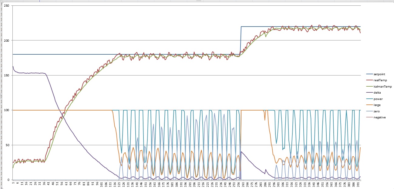
-@Full power it takes about 2 minute to come up to 180 degrees. When the filtered temp actually hits 180 it waits 30 secs and bumps the setpoint to 220 C.
-The 20 degree climb from 180 to 220 takes about 40 seconds.

Optimal soak to reflow time would be 30 seconds.. so I'll be applying some foil to the inside of most of the lid as well to see if I can get the oven performance perfect.
FABRICA MI DIEM, PVNC!
ivan141
LQFP112 - Up with the play
Posts: 148
Joined: Sat Sep 29, 2012 9:16 pm
Location: Rotterdam, the Netherlands

Re: My own reflow controller

Post by ivan141 »

I did some polishing on the fuzzy logic configuration and insulated half of the lid with aluminum tape tonight.
Here's the log:
Image

Changed my fuzzy input sets to add a buffer for small errors and I linked the rules as follows:
IF error IS large THEN output IS max
IF error IS small THEN output IS high
IF error IS zero THEN output IS mid
IF error IS negative THEN output IS off
This in practice makes sure that I hit my setpoint, also the on-off behaviour is gone. Not that it can do much harm, but I prefer
to see the oven dimming rather than just switching on/off after all my troubles with the triac and control algorithms.

The added insulation really has an impact (again). The sprint up to 180 (typical end of soak phase) takes about 40 seconds now,
the ramp up to 220 takes just 20 seconds... Performance is satisfying, I will be proceeding with a reflow profile implementation next.
Test it out for shits and giggles, then perhaps do some user interfacing...
FABRICA MI DIEM, PVNC!
ivan141
LQFP112 - Up with the play
Posts: 148
Joined: Sat Sep 29, 2012 9:16 pm
Location: Rotterdam, the Netherlands

Re: My own reflow controller

Post by ivan141 »

Programmed a crude eutectic reflow profile implementation today.
Here's the log after getting it about right (after 1,5 hours worth of cockups).

Image

It's basically a set of target temps and times and a linear interpolation every second to calculate the next setpoint.
I'll admit it could have been regulated more smoothly, but I only really care about how good it tracks the configured profile. Am well happy with that.
I have the oven ramp down to 0 for 10 secs for controlled ramp down from the reflow zone before sounding the buzzer that reminds me to open the oven.

Need to sleep now, but (hopefully fresh) solder paste is in the fridge so I think tomorrow will be the day I'll find out how good it performs in practice.
FABRICA MI DIEM, PVNC!
User avatar
Fred
Moderator
Posts: 15431
Joined: Tue Jan 15, 2008 2:31 pm
Location: Home sweet home!
Contact:

Re: My own reflow controller

Post by Fred »

Blue is target, green and red are two runs, what's purple? Heater power? Or duty cycle? With mine it was an on/off strategy, state machine based, tuned by thresholds and times. Thermal inertia is huge, though, and with good insulation temp falls pretty slowly with the juice off.
DIYEFI.org - where Open Source means Open Source, and Free means Freedom
FreeEMS.org - the open source engine management system
FreeEMS dev diary and its comments thread and my turbo truck!
n00bs, do NOT PM or email tech questions! Use the forum!
The ever growing list of FreeEMS success stories!
ivan141
LQFP112 - Up with the play
Posts: 148
Joined: Sat Sep 29, 2012 9:16 pm
Location: Rotterdam, the Netherlands

Re: My own reflow controller

Post by ivan141 »

Red is unfiltered temp, green is kalman filtered temp. The thermocouple signal has some significant ripple that I needed to get rid of.
Purple is heater power, which is the percentage of every mains half-sine the lamp is turned on (basically dutycycle).
As you can see the heater works rather fast so not using basic on/off control allows for better control, but this is not far from it at it's current state of tune.
At the moment it looks like on/off control with a provision for cranking up the applied power when required.
I tuned the control parameters for fixed setpoints, not almost continually changing slopes, this last case needs a bit more fettling, but I'm pretty sure it will solder.
FABRICA MI DIEM, PVNC!
User avatar
Fred
Moderator
Posts: 15431
Joined: Tue Jan 15, 2008 2:31 pm
Location: Home sweet home!
Contact:

Re: My own reflow controller

Post by Fred »

Yes, it took me quite a bit of circuit filter fiddling to get my temperature readings stable in my setup. This post mentions it: viewtopic.php?p=26288#p26288

Yeah, your setup seems to have far more potency than my baby oven did :-D On mine the insulation was key to success, and the sequence was pretty much just:

1) On until peak before dry cycle achieved
2) Off until time elapsed for drying (minimal temperature drop due to good insulation)
3) On until peak melt temp achieved
4) Off forever
5) Open door after soak period finished

Is there any reason why it doesn't use a more stable and lower "duty" output in the initial rate-limited ramp, and the dry out hold phase?

If PID is involved you should add "feed forward" or base value which, in this case, would be a 2D lookup of temperature vs duty to hold that temperature upon which it could add some duty to raise the temperature.

The other thing with my setup is that I accidentally bought a mains control device that has a low switching speed, so I couldn't PWM it anyway :-)

Digging up my live run screen shots for comparison with yours.... here you go:

"full power, off at 110C, timer start at 120C, full power again at 2 minutes, off again at 229C, open door 20 seconds later."

Image
DIYEFI.org - where Open Source means Open Source, and Free means Freedom
FreeEMS.org - the open source engine management system
FreeEMS dev diary and its comments thread and my turbo truck!
n00bs, do NOT PM or email tech questions! Use the forum!
The ever growing list of FreeEMS success stories!
Post Reply