RGB dashboard backlight, PCB's are in!
Posted: Mon Oct 01, 2012 10:07 pm
Here's a little project I've been working on for the last few months. This is quite likely the
only forum I visit where people have enough off an understanding of the subject to point
out any flaws.
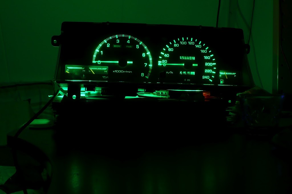
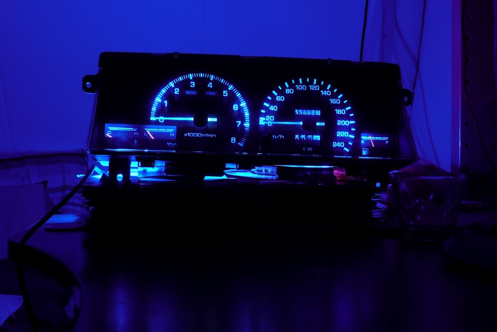
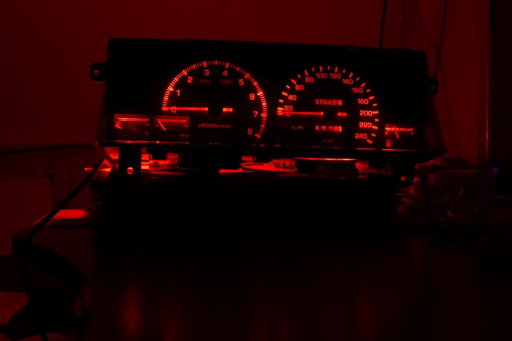
It started out by trial fitting a couple 12mm RGB led's in my ae86 cluster and trying to see
if that would fly (it didn't, hot spots and not enough light).
Disappointed with that result I figured I might as well dabble a bit in PCB design and just slap
some rgb led's on a pcb with some led-driver IC's. Not exactly rocket science, now is it?
Reality bites, as they say, and it ended up making my GF very cross with me some evenings,
sweating over some PCB routing conundrum or other. Anyway, after a few weeks of mulling
over what more I could do to improve the design, I decided that I wasnt going to come up with new
ideas. If you don't take action, nothing ever gets finished, so the gerbers have been sent off to china
(iteadstudio) for production last week (should be in by the end of the month I hope).
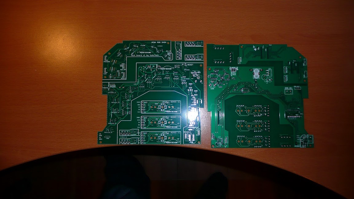
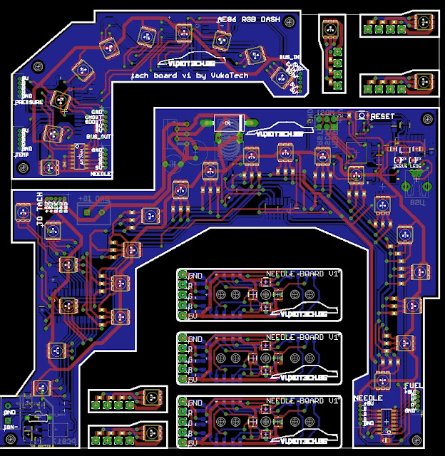
Here's the 'panelized' board I sent out.
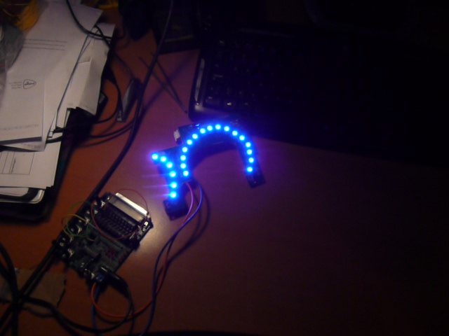
Here's holding my fingers crossed that I will actually get it to do something. The firmware shouldnt be
too challenging, apart from some elegant way to handle animated sequences.
Some general specs:
-Atmel ATMEGA328 in smd package for control (overkill, but I like some room for my not too optimised code).
-LM2576 5v 3A switching supply (I know you guys love linear, but I dont feel like melting my plastic dash).
-WS2803/2801 24 bit / rgb channel led drivers.
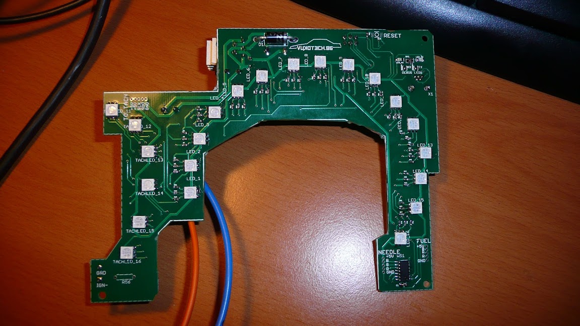
-Pixel precision on the tach side, slaved configuration on the speedo.
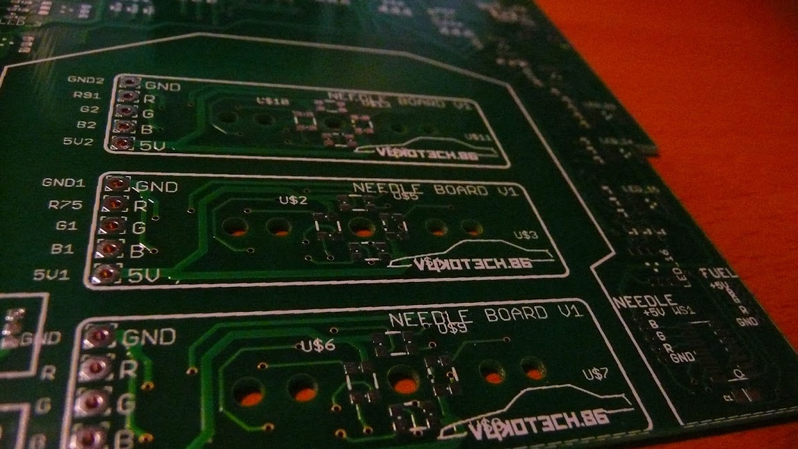
-Really small RGB led's (4) on a special needle board that slots in the place of the old light guides.
-Small PLCC RGB led boards for auxiliary lighting of pressure, temp and fuel gauge.
-FTDI based USB micro interface (in an impossible position, I know, it couldnt be helped).
-Optocoupler separated input circuit for tach signal (coil-), connected to an interrupt for a simple counting rpm measurement scheme.
only forum I visit where people have enough off an understanding of the subject to point
out any flaws.
It started out by trial fitting a couple 12mm RGB led's in my ae86 cluster and trying to see
if that would fly (it didn't, hot spots and not enough light).
Disappointed with that result I figured I might as well dabble a bit in PCB design and just slap
some rgb led's on a pcb with some led-driver IC's. Not exactly rocket science, now is it?
Reality bites, as they say, and it ended up making my GF very cross with me some evenings,
sweating over some PCB routing conundrum or other. Anyway, after a few weeks of mulling
over what more I could do to improve the design, I decided that I wasnt going to come up with new
ideas. If you don't take action, nothing ever gets finished, so the gerbers have been sent off to china
(iteadstudio) for production last week (should be in by the end of the month I hope).
Here's the 'panelized' board I sent out.
Here's holding my fingers crossed that I will actually get it to do something. The firmware shouldnt be
too challenging, apart from some elegant way to handle animated sequences.
Some general specs:
-Atmel ATMEGA328 in smd package for control (overkill, but I like some room for my not too optimised code).
-LM2576 5v 3A switching supply (I know you guys love linear, but I dont feel like melting my plastic dash).
-WS2803/2801 24 bit / rgb channel led drivers.
-Pixel precision on the tach side, slaved configuration on the speedo.
-Really small RGB led's (4) on a special needle board that slots in the place of the old light guides.
-Small PLCC RGB led boards for auxiliary lighting of pressure, temp and fuel gauge.
-FTDI based USB micro interface (in an impossible position, I know, it couldnt be helped).
-Optocoupler separated input circuit for tach signal (coil-), connected to an interrupt for a simple counting rpm measurement scheme.