How to read RPM - diy tachometer
Posted: Wed Jan 22, 2014 11:46 pm
In this article I will explain how I hacked into my car harness in order to read current RPM. This approach is not universal and there are no guarantees - this article only applies to my car and you should not attempt doing anything like that to yours.
A bit of technical background first: the car I have hacked was sold in US as Ford Aspire, it was made in South Korea and it's Mazda design with some Mitsubishi components. Not your average F150 exactly This car uses Hall effect crankshaft position sensors (no idea how that works). So I could have used the same approach for something like Mazda Protege or even a Miata from the 90's - the younger cars would have sensors based on Variable reluctance and that would be a different story.
When I open the hood, I see a distributor like the one on the picture

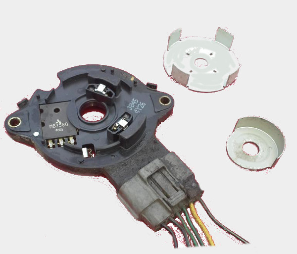
If I would have decided to break this distributor and look inside, I would see something like

That tin wheel spins with the crankshaft and that's what make the CKP signal. If I would keep taking it apart, I would see the actual sensors and the other wheel - the smaller wheel is in charge of CID signal.
Does not really matter what CKP and CID signals are. We only care that even while the car has a 12 volts battery, most of the sensors and the stock ECU run on 5 volts. Somewhere in my harness where are two 5 volts wave signals which look like this:
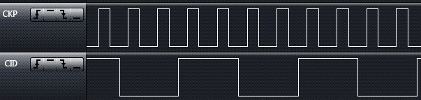
That's it. We can wire this signal right into the any 5v tolerant microcontroller. Just to be a bit safer, we will put a 1n4001 diode between the harness and the microcontroller.
So, let's get something done. Let's take a STM32F4DISCOVERY dev board - that's a $15 board based on some stm32f4 microcontroller running at 168MHz.
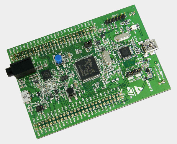
That's actually a lot of cheap computation power.
As is, microcontrollers are not exactly super friendly - ChibiOS/RT would help us, we will let it take care of the the lower level. We will use serial-over-usb to output data - so, mini-usb cable would be used to flash & power the board and the micro-usb cable would be used for serial. If you made it to here you probably know what serial is.
It's not much code, it's quite self-explanatory:

(the code is a picture simply because I wanted to keep the coloring)
A bit of technical background first: the car I have hacked was sold in US as Ford Aspire, it was made in South Korea and it's Mazda design with some Mitsubishi components. Not your average F150 exactly
When I open the hood, I see a distributor like the one on the picture
If I would have decided to break this distributor and look inside, I would see something like
That tin wheel spins with the crankshaft and that's what make the CKP signal. If I would keep taking it apart, I would see the actual sensors and the other wheel - the smaller wheel is in charge of CID signal.
Does not really matter what CKP and CID signals are. We only care that even while the car has a 12 volts battery, most of the sensors and the stock ECU run on 5 volts. Somewhere in my harness where are two 5 volts wave signals which look like this:
That's it. We can wire this signal right into the any 5v tolerant microcontroller. Just to be a bit safer, we will put a 1n4001 diode between the harness and the microcontroller.
So, let's get something done. Let's take a STM32F4DISCOVERY dev board - that's a $15 board based on some stm32f4 microcontroller running at 168MHz.
That's actually a lot of cheap computation power.
As is, microcontrollers are not exactly super friendly - ChibiOS/RT would help us, we will let it take care of the the lower level. We will use serial-over-usb to output data - so, mini-usb cable would be used to flash & power the board and the micro-usb cable would be used for serial. If you made it to here you probably know what serial is.
It's not much code, it's quite self-explanatory:
(the code is a picture simply because I wanted to keep the coloring)