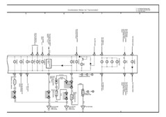
2003 Toxic Tacoma

Post your project vehicles here! One thread per vehicle please.
User avatar
ToxicGumbo
LQFP144 - On Top Of The Game
Posts: 474
Joined: Tue Jan 03, 2012 8:37 pm
Location: Manhattan, KS. USA

Re: 2003 Toxic Tacoma

Post by ToxicGumbo »

Today, two angled USB cable connectors came in. That potentially resolves the ill-fitting-USB cable issue. I spent some time trying to get audio feedback working in the theme, but that appears to be an ongoing issue for many. The RTC is working again now, too, and is hotglued & 3M-taped back into place.

Yesterday, I reached out to thank Kevin Uhlir, the developer of PiClock, and pointed him back here to the forum. He responded with this meaty response:
Looks like a fun project. I'd love to see how it develops. You might want to buy a cheap serial gps unit, rather than trying to get the phone to give you its position. You'd have to do some kind of app in the phone.

Here's a couple of hints for python qt4 serial....

http://stackoverflow.com/questions/7719 ... d-pyserial

http://stackoverflow.com/questions/1837 ... w-pyserial

GPS

http://www.ebay.com/itm/New-UART-Serial ... 1529744304


You'd have to do polling with a timer Pyserial/inWaiting(), store the lat long for the next update.

The radar is layered... background and marker layers are only retrieved once. The radar layer is retrieved every 10 minutes.

If you're using a Pi3, redoing the background and marker layers more often shouldn't be a problem.

Noaa alerts -- xml alerts are by zone, or county. https://alerts.weather.gov/

Google can help with finding counties... http://stackoverflow.com/questions/5864 ... a-lat-long

But it looks like you could get alerts from weather underground too: https://www.wunderground.com/weather/ap ... ata/alerts
(remember to pull this along with the forecast, or it will count against the api call count.


Kevin
User avatar
ToxicGumbo
LQFP144 - On Top Of The Game
Posts: 474
Joined: Tue Jan 03, 2012 8:37 pm
Location: Manhattan, KS. USA

Re: 2003 Toxic Tacoma

Post by ToxicGumbo »

After being mercilessly ridiculed by Fred here about my power management for peripheral devices, I ripped out the 3-way cigarette lighter socket and shelved the cheap 12-to-5VDC power converters for USB. In their place went a Walmart device with power protection, one cigarette lighter socket, and two USB ports, with direct wiring to vehicle ACC. This device is substantially better suited for the situation and only powers the hub and CB.

However, the last time the Pi was hooked up in the car, I was having some power issues with the Mausberry arrangement. The Pi kept reporting low-current conditions even though the USB cable handles higher current and the Mausberry allows up to 3A. (For reference, the Pi itself is fused at 2A and the touchscreen pulls under 1A). The two most likely sources behind this: Mausberry-to-battery wiring or the Mausberry-to-Pi USB cable.

The former runs through the dome light fuse (rated at 15A) and might not be a decent gauge to handle 3A through the radio wiring. Strangely, I found the fuse burned out today even though things were working at last attempt. Perhaps the wire run is degraded at some point.

The latter is possible, too, given the reports people make on the micro cables and how they only seem to work for several weeks before having charging issues.

I'm going to run a separate battery line and see if the warnings go away. This is frustrating since the Pi shuts off and I've been wanting to update my FreeEMS firmware for weeks. To do that, I'll bring my old EeePC in to the office tomorrow and give that a shot.

Ultimately, I wish the Raspberry Pi didn't rely on USB ports as a power source, especially since the device frequently exceeds the standard ratings for those ports. You'd think there might have been some on-board terminals for such situations.
User avatar
Fred
Moderator
Posts: 15431
Joined: Tue Jan 15, 2008 2:31 pm
Location: Home sweet home!
Contact:

Re: 2003 Toxic Tacoma

Post by Fred »

Is there really no header pins you can feed a solid 5V into? If there is one, intended for output to peripherals, it may well be on the same exact bus, and it may well be suited to back feeding solid 5V into without harm. I'd consult a forum or manual or both before doing it, but might be worth a shot if the only other option is USB micro connectors. 3A isn't a huge amount, but it's a lot for the tiny pins in those.
DIYEFI.org - where Open Source means Open Source, and Free means Freedom
FreeEMS.org - the open source engine management system
FreeEMS dev diary and its comments thread and my turbo truck!
n00bs, do NOT PM or email tech questions! Use the forum!
The ever growing list of FreeEMS success stories!
User avatar
ToxicGumbo
LQFP144 - On Top Of The Game
Posts: 474
Joined: Tue Jan 03, 2012 8:37 pm
Location: Manhattan, KS. USA

Re: 2003 Toxic Tacoma

Post by ToxicGumbo »

There is the 5V GPIO header and I even put in a jumper on the PiCAN as that location routes directly to the GPIO. However, it would need to be a very clean and fused 5V:

A more technical (and of course dangerous) way to power the Pi is directly via the GPIO. It should be noted that, unlike the Micro-USB port, there is no regulation or fuse protection on the GPIO to protect from over-voltage or current spikes.

That--with a fuse and and higher gauge wiring--might have to be the solution.
User avatar
Fred
Moderator
Posts: 15431
Joined: Tue Jan 15, 2008 2:31 pm
Location: Home sweet home!
Contact:

Re: 2003 Toxic Tacoma

Post by Fred »

So how exactly is the protection on the USB connectors implemented? I'm sceptical of the above quote.
DIYEFI.org - where Open Source means Open Source, and Free means Freedom
FreeEMS.org - the open source engine management system
FreeEMS dev diary and its comments thread and my turbo truck!
n00bs, do NOT PM or email tech questions! Use the forum!
The ever growing list of FreeEMS success stories!
User avatar
ToxicGumbo
LQFP144 - On Top Of The Game
Posts: 474
Joined: Tue Jan 03, 2012 8:37 pm
Location: Manhattan, KS. USA

Re: 2003 Toxic Tacoma

Post by ToxicGumbo »

Here's one vague reference to the GPIO's state: http://elinux.org/RPi_Low-level_periphe ... _GPIO_pins

Here's the most detailed information I could find on power distribution: http://elinux.org/RPi_Hardware#Power

This latter one states the following:
As the 5 V rail is brought out in the GPIO pins, you can power the Raspberry Pi from there too. You should mind however, that those are behind the power protection circuitry, so you should provide your own.
and
The board provides a polarity protection diode, a voltage clamp, and a self-resetting semiconductor fuse.
It looks like they used to have polyfuses on each USB port and have changed that design.

Edit: Of interest to me at the moment: http://raspberrypi.stackexchange.com/qu ... /9299#9299
User avatar
ToxicGumbo
LQFP144 - On Top Of The Game
Posts: 474
Joined: Tue Jan 03, 2012 8:37 pm
Location: Manhattan, KS. USA

Re: 2003 Toxic Tacoma

Post by ToxicGumbo »

Some IR sensors I'm using claim 5mA x 4 = 20mA. Need to check what's already using 3.3V, which appears to have a max of 50mA as mentioned in the "Edit" link above.
User avatar
ToxicGumbo
LQFP144 - On Top Of The Game
Posts: 474
Joined: Tue Jan 03, 2012 8:37 pm
Location: Manhattan, KS. USA

Re: 2003 Toxic Tacoma

Post by ToxicGumbo »

It occurred to me this morning, while on the toilet no less, that soon I'll not only be logging FreeEMS data at each key-on, but will also have a GPS unit powered at the same time. So why not dump coordinate data to a separate file, similarly named, to match FreeEMS logs? That way I not only have the details of each drive, but also can place the vehicle in context.

Here's one decent Arduino-oriented link via Google: http://www.toptechboy.com/arduino/lesso ... gle-earth/

Seems like stepped coordinates and altitude would be fun to monitor in association with vehicle dynamics.
User avatar
Fred
Moderator
Posts: 15431
Joined: Tue Jan 15, 2008 2:31 pm
Location: Home sweet home!
Contact:

Re: 2003 Toxic Tacoma

Post by Fred »

Image

DO IT.
DIYEFI.org - where Open Source means Open Source, and Free means Freedom
FreeEMS.org - the open source engine management system
FreeEMS dev diary and its comments thread and my turbo truck!
n00bs, do NOT PM or email tech questions! Use the forum!
The ever growing list of FreeEMS success stories!
User avatar
ToxicGumbo
LQFP144 - On Top Of The Game
Posts: 474
Joined: Tue Jan 03, 2012 8:37 pm
Location: Manhattan, KS. USA

Re: 2003 Toxic Tacoma

Post by ToxicGumbo »

I haven't worked on the Pi goodies for a little while now due to other factors. Ultimately, I still need to resolve hardware concerns before wrapping up software and the GPS logging falls somewhere in the middle as USB devices will need to be hard referenced during boot for consistent device mapping. Without that, software can't even recognize the correct devices as race conditions occur during boot and items are assigned different device IDs each time. Arbitrarily throw in a flash drive or somesuch and that would further complicate matters. I'm resolved to the fact that winter or not, I just need to get the hardware, in full, bolted in and working before correcting software from within an idling truck.

This means:
  • Fix electrical. I'm not keen to run 12V constant through the firewall and into the dash, but it is what it is.
  • Complete the IR screen surround and trust that 20mA won't overload the 3.3V GPIO pin that's already lending voltage to the PiCAD2 and RTC. More later on this.
  • Run raw wires from the PiCAN2 CAN breakout to a DB9 male connector. Sadly, I bought female by mistake.
  • Remove the HDMI cabling and install an ethernet cable. Change of plans for the gauge cluster.
Once all of that is done, the entire thing can be sealed and only software is left to resolve. This will mostly wrap up stage 1 (ECU) and 2 (HMI) and start sage 3 (gauge cluster).


I received a Pi Zero for Christmas and promptly spent more money on accessories. Though the intention was to use the Zero for staging software updates and changes to the Pi3 HMI unit, my long-term goal of creating an LCD gauge cluster has changed. It was initially going to be an HDMI screen off the Pi3 as part of a dual-head configuration. This sort of arrangement poses a number of problems that all go away if, instead, the LCD is driven by a Pi Zero that's preloaded with NodeJS and reads FreeEMS serial comms via TCP/IP from the HMI unit. Likewise, internet data can be IP forwarded from the HMI unit and all gauge display necessities remain on the actual gauge unit (the Pi Zero) instead of through a delicate dual-headed arrangement on an increasingly bogged down Pi3. The Pi Zero also presents a full array of GPIO pins for handing stepped-down indicator lamps.

After looking through wiring schematic, here's what will need to be interfaced (and can be pin-sensed at 3.3V and displayed via software):

Meters:
  1. Tach: From FreeEMS comms
  2. Speed: From VSS or accelerometer
  3. Fuel: From sender
  4. Water Temp: From FreeEMS comms
Rather than rely on associated alert lamps for the above meters, software alerts and actions can be created based on low-voltage levels for the absent meters. Meter voltage ranges are usually provided in repair manuals.

Lamps:
  1. Oil, low
  2. ABS
  3. MIL/CEL
  4. Washer fluid
  5. Seat belt
  6. Turn L
  7. Turn R
  8. High beam (headlights)
  9. Brake, low/parking brake
  10. SRS
  11. Overdrive, off
  12. Charge system
There might be a fuel open sockets for other sensors (transmission temp, 4WD engage, etc.) which aren't available on my truck, but have pre-existing wiring elsewhere. That might come in handy for custom sensor wiring later on.


Here are a few examples of cheap options to change 12-15VDC to 3.3V:
Wiring diagram for the the 2000-2004 Tacoma gauge cluster:
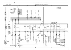
Image
Image


To power the Pi Zero, it would be nice to simply hang it off the existing Mausberry system I have for safe shutdown. For the display, that would be switched and requires 12VDC, approx 2.5-3A.
Post Reply