Vertical Bandsaw Project Ideas & Parts Collection
Posted: Tue Aug 27, 2019 9:19 am
And one day, build.
The only single-phase metal cutting bandsaw machineryhouse sells is $4370 NZ inc GST and has: https://www.machineryhouse.co.nz/B010A
power 0.37kw / 0.5hp
speed range of 20-90 m/min
throat of 310mm
height of 175mm
blade 2510mm
weight 225kg
So I bought some 18" motorcycle wheels to use as bandsaw wheels for 150nzd: https://twitter.com/FredCookeNZ/status/ ... 4241274881

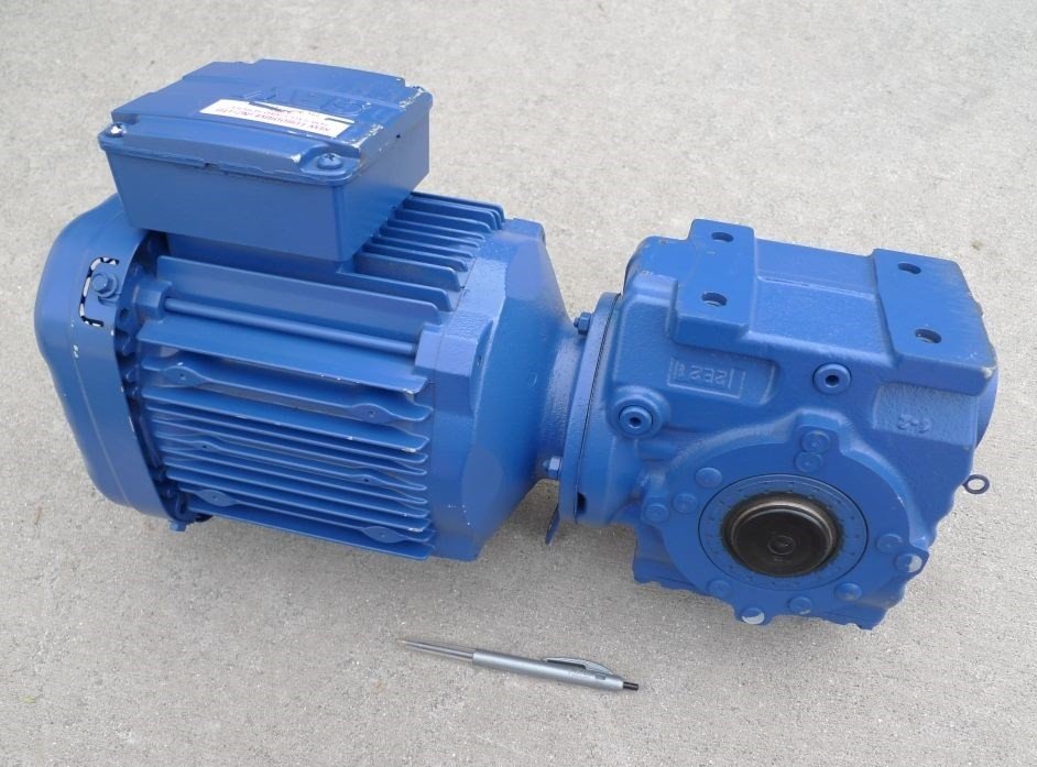
And have my eye on a $200+ brand new high quality NOS geared motor with 0.55kw 3/4hp that spins 274 RPM.
What I'm wondering is if I lose say 2 inches on the wheels after machining/mods then what lineal speed will I get direct coupling that motor to the lower pulley? Let's find out.
16" in mm is 406.4, let's call it 400 D, 200 R, 400 throat
PI * R = C
3.14159 * 200 = 628.3mm, let's call it 630 or 0.63m
274 * 0.63 = 172.6 m/min
Which will still need a step down to achieve metal speeds of at least 2:1 and at most 8:1 but a VFD can be used to achieve a significant speed reduction (or minor speed increase) without loss of torque or any other issue.
Wood bandsaws seem to run about 500-1000m/min speeds and much higher power levels. Ignoring the power requirements of high speed because lower end saws have similar to my intended power, a step up of between 3:1 and 6:1 is needed.
Stepped pulleys with 6" down to 2" on both sides would give the bare minimum reduction/increase of 3:1 but using a two-belt approach could yield better pulley sizes and better ratios or same pulley sizes and more extreme ratios of 9:1
So if I just provide 3:1 up, 1:1, and 3:1 down then I should have decent performance on wood and great performance on stainless steel and everything in between. If I can make that 4:1 and maybe have 2:1 in between as well, that'd be even better. Speed guide from above model: https://twitter.com/FredCookeNZ/status/ ... 5895561216

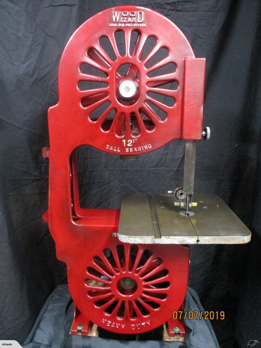
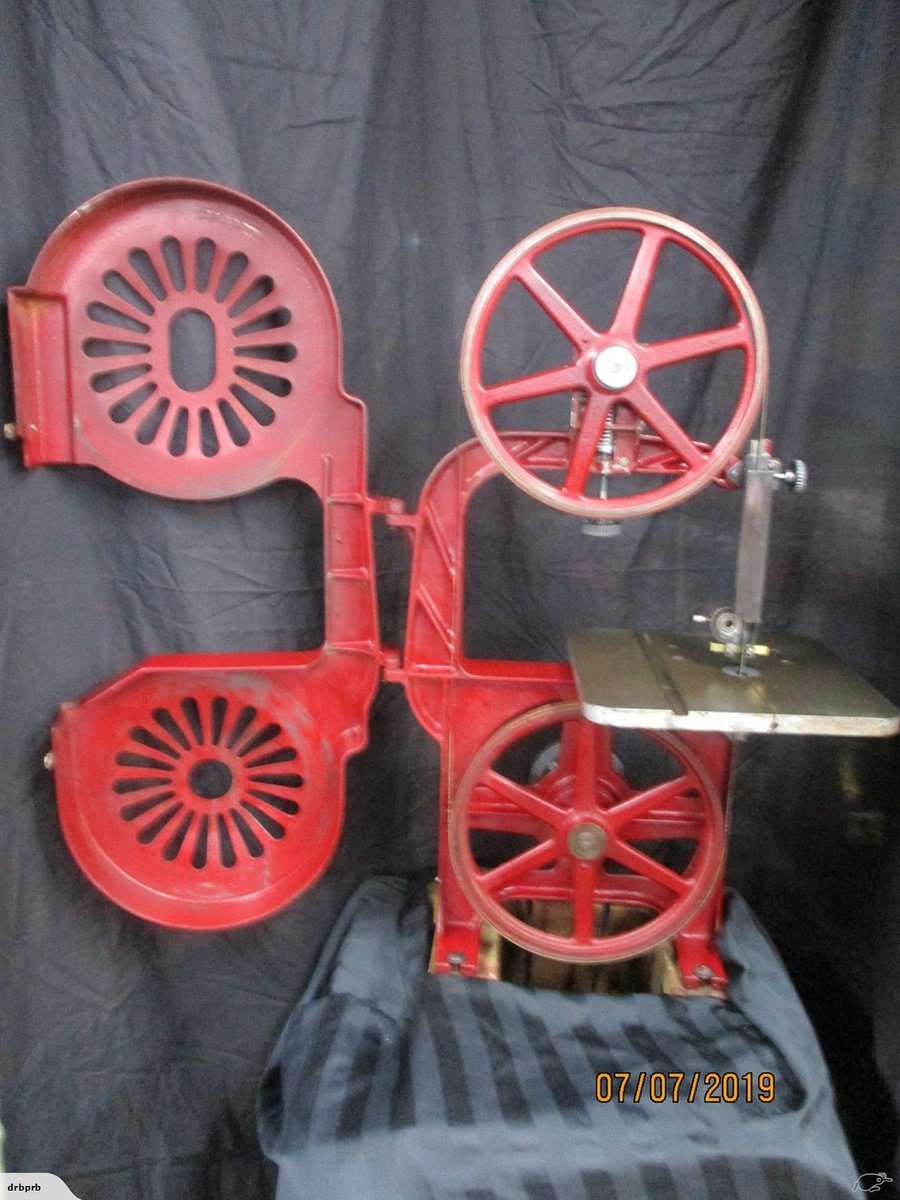
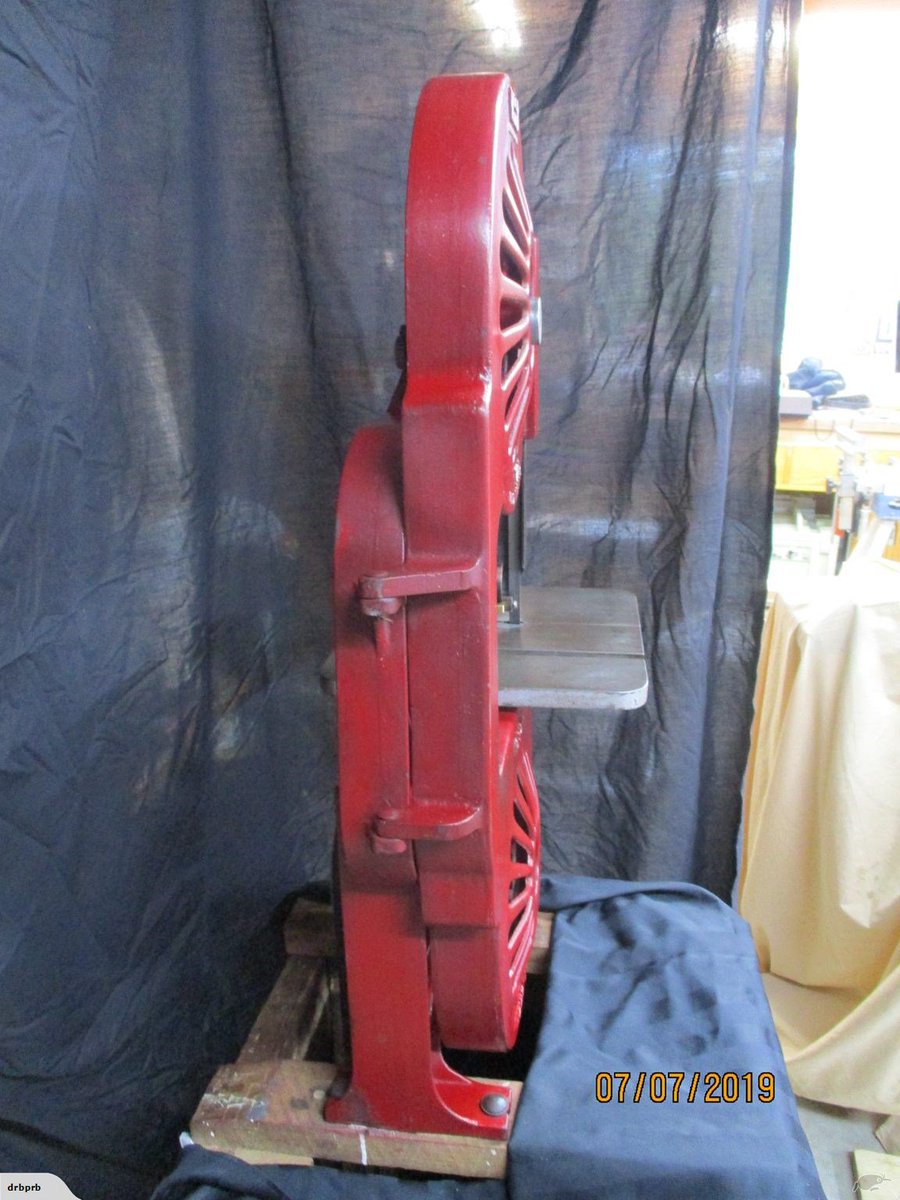
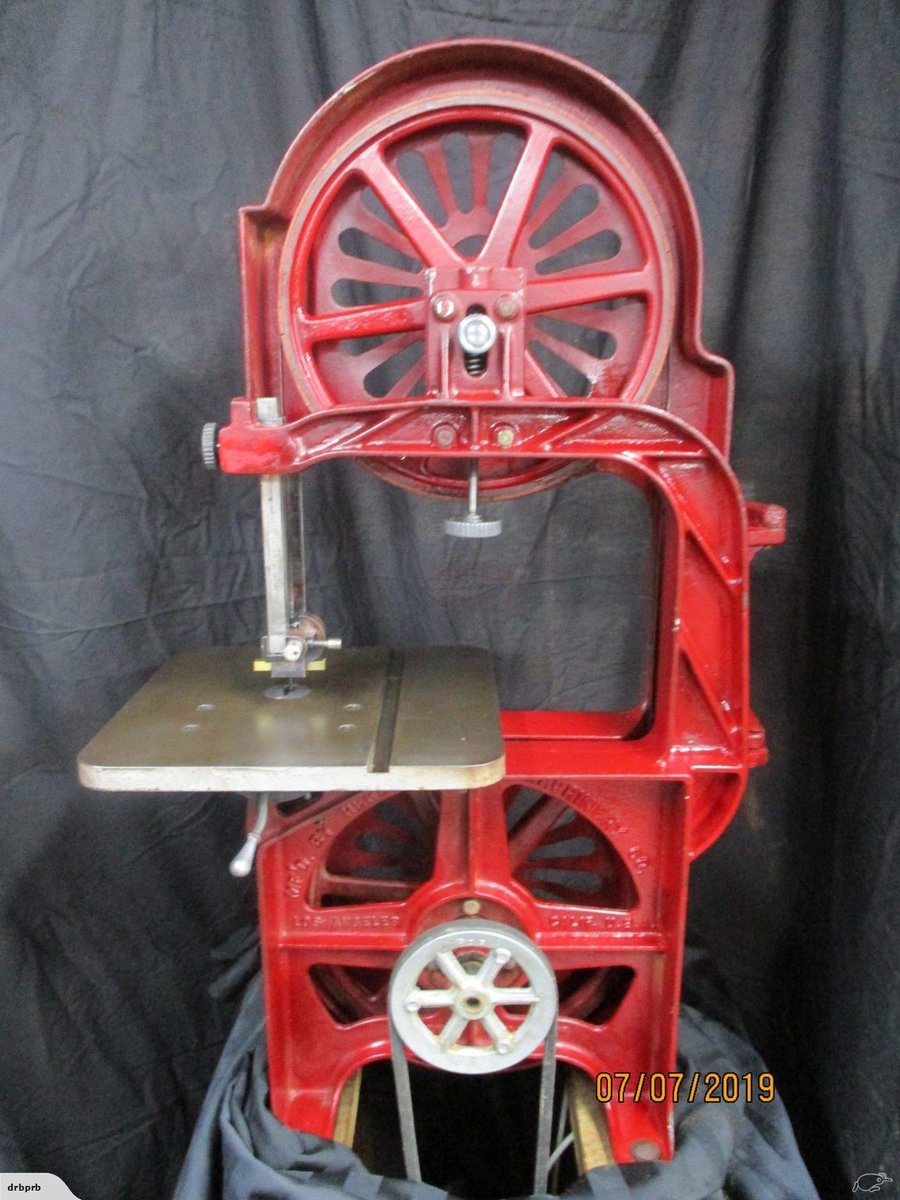
Style wise, it'd be nice to have round covers over the top and bottom wheels, something like this sweet old thing: https://twitter.com/FredCookeNZ/status/ ... 2781006848
Other random stuff to consider:
1) Brushes on the wheels to keep them clean
2) Contact material, inner tube rubber or cork bonded on?
3) Dust/chip extraction/collection
4) Blade cooling via air
5) Coolant supply and capture/recycling and removal from blade before hitting wheels if so
6) Blade guide design
7) Blade guide height adjust design
8) Blade tension design
9) Belt tension design if belts used
10) Frame design
11) Table design with tilt and trunnion design
12) Blade cover near frame
13) Wheel mods to get max diameter for max throat depth
14) Double sheer wheel support design
And probably 50 other things.
Note, I have the steel for the press that I didn't use and ended up buying a used frame for. Highly likely to be used for this. IIRC 80x80x5 box 1800 tall or so? Should be ample.
The only single-phase metal cutting bandsaw machineryhouse sells is $4370 NZ inc GST and has: https://www.machineryhouse.co.nz/B010A
power 0.37kw / 0.5hp
speed range of 20-90 m/min
throat of 310mm
height of 175mm
blade 2510mm
weight 225kg
So I bought some 18" motorcycle wheels to use as bandsaw wheels for 150nzd: https://twitter.com/FredCookeNZ/status/ ... 4241274881
And have my eye on a $200+ brand new high quality NOS geared motor with 0.55kw 3/4hp that spins 274 RPM.
What I'm wondering is if I lose say 2 inches on the wheels after machining/mods then what lineal speed will I get direct coupling that motor to the lower pulley? Let's find out.
16" in mm is 406.4, let's call it 400 D, 200 R, 400 throat
PI * R = C
3.14159 * 200 = 628.3mm, let's call it 630 or 0.63m
274 * 0.63 = 172.6 m/min
Which will still need a step down to achieve metal speeds of at least 2:1 and at most 8:1 but a VFD can be used to achieve a significant speed reduction (or minor speed increase) without loss of torque or any other issue.
Wood bandsaws seem to run about 500-1000m/min speeds and much higher power levels. Ignoring the power requirements of high speed because lower end saws have similar to my intended power, a step up of between 3:1 and 6:1 is needed.
Stepped pulleys with 6" down to 2" on both sides would give the bare minimum reduction/increase of 3:1 but using a two-belt approach could yield better pulley sizes and better ratios or same pulley sizes and more extreme ratios of 9:1
So if I just provide 3:1 up, 1:1, and 3:1 down then I should have decent performance on wood and great performance on stainless steel and everything in between. If I can make that 4:1 and maybe have 2:1 in between as well, that'd be even better. Speed guide from above model: https://twitter.com/FredCookeNZ/status/ ... 5895561216
Style wise, it'd be nice to have round covers over the top and bottom wheels, something like this sweet old thing: https://twitter.com/FredCookeNZ/status/ ... 2781006848
Other random stuff to consider:
1) Brushes on the wheels to keep them clean
2) Contact material, inner tube rubber or cork bonded on?
3) Dust/chip extraction/collection
4) Blade cooling via air
5) Coolant supply and capture/recycling and removal from blade before hitting wheels if so
6) Blade guide design
7) Blade guide height adjust design
8) Blade tension design
9) Belt tension design if belts used
10) Frame design
11) Table design with tilt and trunnion design
12) Blade cover near frame
13) Wheel mods to get max diameter for max throat depth
14) Double sheer wheel support design
And probably 50 other things.
Note, I have the steel for the press that I didn't use and ended up buying a used frame for. Highly likely to be used for this. IIRC 80x80x5 box 1800 tall or so? Should be ample.