
The thread has been running for almost 2 years now - I stumbled across it some time ago.
(warning - it's 59 pages long by now, and I couldn't stop reading...)
http://www.rx7club.com/build-threads-29 ... ld-974831/
4 Rotor FC Build
Re: 4 Rotor FC Build
That is some EXTREME machining O.O I would never stand in front of that lathe, spinning that shaft at ~500rpm. Nice find!

Re: 4 Rotor FC Build
Ugh, he's using a knock-off MS2 called KDFI from Holland on his RS FD, yuck.
" If I had to choose again I probably would've gone with an MS3 Pro." :-/
It's not too late! He's not run it yet! :-)
In terms of his setup, it's ultra simple:
He has the rotors paired for "big bang" effect, and only one injector per rotor, so he could actually run that engine properly with a mere 4 CPU outputs!
If he wanted trimmability, and trailing spark, and staged injection, he'd need 16 outputs, but it wouldn't provide much benefit over 4, that's for sure (except the staged injection).
There goes my Sunday afternoon: http://www.youtube.com/watch?v=zXeRB-3nDR8
Fred.
DIYEFI.org - where Open Source means Open Source, and Free means Freedom
FreeEMS.org - the open source engine management system
FreeEMS dev diary and its comments thread and my turbo truck!
n00bs, do NOT PM or email tech questions! Use the forum!
The ever growing list of FreeEMS success stories!
FreeEMS.org - the open source engine management system
FreeEMS dev diary and its comments thread and my turbo truck!
n00bs, do NOT PM or email tech questions! Use the forum!
The ever growing list of FreeEMS success stories!
-
John Huijben
- TO92 - Vaguely active
- Posts: 1
- Joined: Mon Sep 01, 2014 7:04 pm
Re: 4 Rotor FC Build
I've been notified of this thread and want to explain.
Yes, the ecu used on the FD was a knock off MS2. I wasn't aware of what was what at the time and needless to say I will never use that again.
About the 4-rotor, you are wrong. The rotors are not paired for a big bang affect. Every rotor is 90 degree phased from each other, with the firing order being 1-3-2-4. The ecu used is a microsquirt module using msextra firmware. There are 4 ignition outputs and 4 injection outputs. There is no split timing, and no staged injection, but there is no need for either because the engine is normally aspirated.
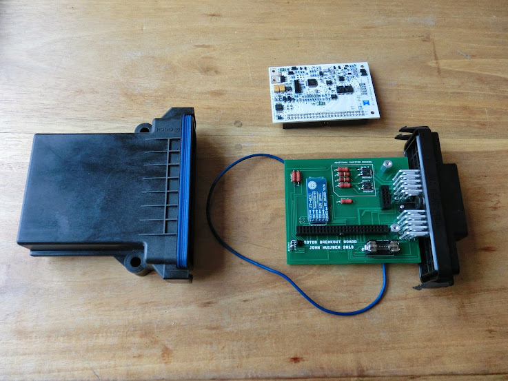
This is the ecu, I'm not a fan of the MS2's board, or it's non waterproof housing and connector. So I'm using a waterproof cinch housing, a self-designed breakout board, and the microsquirt module. I've assembled and installed multiple ecu's like this
A video of the car being run on my homemade dyno
https://www.youtube.com/watch?v=6o6YeCMg7XE
Yes, the ecu used on the FD was a knock off MS2. I wasn't aware of what was what at the time and needless to say I will never use that again.
About the 4-rotor, you are wrong. The rotors are not paired for a big bang affect. Every rotor is 90 degree phased from each other, with the firing order being 1-3-2-4. The ecu used is a microsquirt module using msextra firmware. There are 4 ignition outputs and 4 injection outputs. There is no split timing, and no staged injection, but there is no need for either because the engine is normally aspirated.
This is the ecu, I'm not a fan of the MS2's board, or it's non waterproof housing and connector. So I'm using a waterproof cinch housing, a self-designed breakout board, and the microsquirt module. I've assembled and installed multiple ecu's like this
A video of the car being run on my homemade dyno
https://www.youtube.com/watch?v=6o6YeCMg7XE
Re: 4 Rotor FC Build
Neat! :-) I can't even remember why I thought that, and I don't have time right now to re read 60+ pages to figure it out. Thanks for popping over and setting the record straight :-)John Huijben wrote:About the 4-rotor, you are wrong. The rotors are not paired for a big bang affect. Every rotor is 90 degree phased from each other, with the firing order being 1-3-2-4. The ecu used is a microsquirt module using msextra firmware. There are 4 ignition outputs and 4 injection outputs. There is no split timing, and no staged injection, but there is no need for either because the engine is normally aspirated.
Fred.
DIYEFI.org - where Open Source means Open Source, and Free means Freedom
FreeEMS.org - the open source engine management system
FreeEMS dev diary and its comments thread and my turbo truck!
n00bs, do NOT PM or email tech questions! Use the forum!
The ever growing list of FreeEMS success stories!
FreeEMS.org - the open source engine management system
FreeEMS dev diary and its comments thread and my turbo truck!
n00bs, do NOT PM or email tech questions! Use the forum!
The ever growing list of FreeEMS success stories!